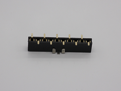
Pin Header is a kind of connector, which is widely used in electronic, electrical, instrument PCB circuits, its function is to be blocked or isolated between circuits, it acts as a bridge, and performs current or signal transmission tasks , usually used with the queue bus to form connections on the board; it can also be used with electronic terminals to form line connections; it can also be used alone for inter-board connections.

What are the performance characteristics of the pin header?
1. The convenience of operation and the mechanical strength of soaking are also important factors. The connector is usually the interface for the communication between the PCB motherboard and the external components. The pin header is very resistant, and sometimes it will not be damaged when it encounters considerable external force.
2. Components assembled by through-hole technology are much more reliable than corresponding SMT components. Resists the PCB easily even with hard pulling, squeezing or heat shock.
3. The pin header processing used for field wiring in the industrial field is generally a high-power component, which can meet different transmission high-voltage and high-current requirements.
4. These advantages weaken as the adhesion of the components to the PCB decreases. The characteristics of the pin header components are that they are carefully designed and easy to attach. There are obvious differences in size and assembly form with the through-hole pins.
5. The needle row has the strength of resistance. Refers to the ability to withstand the rated test voltage between the matching pins, between the contacts or between the contacts and the housing.
6. The general matching pin and female can adapt to the attenuation caused by electromagnetic interference and the shielding ability of electromagnetic interference.
7. The contact resistance of the needle is small, and the contact resistance can be as small as tens of milliseconds.
What should I pay attention to when using pin headers?
1. In the small-signal circuit for pin headers and color-matched connectors, pay attention to the required conditions for the given contact resistance index. Because, the contact surface of the dipping and color matching joints will adhere to the oxide layer, oil and other debris. Otherwise, because the two contact surfaces of the dipping and color matching joints will produce film resistance, the color matching will be damaged.
2. If the thickness of the film layer of the pin header and color matching connector increases, the resistance will increase rapidly, but the film layer will become a bad conductor. However, under high contact pressure, the membrane layer of matching needles and color matching joints will be mechanically ruptured, and under high voltage and high current, electric shock will occur. Therefore, it is not suitable to use through, through, pluck, and hair connectors to increase the thickness of the film layer.
3. The conductor resistance index of needle matching and color matching joints refers to contact resistance, which mainly includes contact resistance and contact resistance to conductors. Moreover, when the conductor resistance is small, the conductor resistance in the circuit is called contact resistance.
How to ensure the quality of pin headers?
1. Anti-static, needle matching, color matching, and electronic display assembly plants must have good anti-static measures.
2. Thermal design The pin header and
Female Header generate heat when working. Too high temperature will affect the attenuation speed and stability of the LED. Therefore, the thermal design of the PCB board and the ventilation thermal design of the box will affect the performance of the LED.
3. The nominal current of the design current value pin header is 20 mA, and it is generally recommended that the current should not exceed 80% of the nominal value. Especially for displays with small dot pitch, the current value is also reduced due to poor thermal conditions.
4. The temperature and time of wave soldering should strictly control the temperature and furnace time of the wave front. The preheating temperature does not exceed 1005, does not exceed 120, the preheating temperature rises softly, the welding temperature is 2455, and the welding time does not exceed 3 seconds.
5. The pin header controls the verticality of the lamp. For the in-line pin arrangement, it is necessary to have sufficient process technology to ensure that the LEDs are perpendicular to the PCB board when passing through the furnace.
